This week was the final week to submit the Proposal Report. I send my Proposal Report to Dr. Reyasudin on 29/5/2019. After that, he check for the plagiarism and I need to send the front page and similarity report of my proposal. My plagiarism for proposal report was under the condition that being set. Alhamdulillah, in these 16 weeks I learn a lot o things to make sure my project will success. I learnt about how to use the SketchUp software. I also went to Cura 3D printing workshop to know how to use the 3D printing for my turbine. I learnt a lot of thing about micro power generator. There a lot of idea that came to me when I read from previous studies and in tend to improvise their works.
Special thanks I bet to Dr. Reyasudin for supervising me along this FYP1 period. I hope Dr, Reyasudin can help me further in my journey for FYP 2 next semester. Although FYP 2 start next semester, I will continue to plan my project starting my holiday of semester break. i wil do a lot of research on how to increase the development of my micro power generator in water pipe.
Thursday, May 30, 2019
Friday, May 24, 2019
Week 15
Project Sketch
For this week, I focus on the project sketch for my project. This to make sure that when the FYP2 started, I can do it straight away without waiting to make it. I also make the circuit diagram for the connection between voltage sensor, Arduino Uno, and the LCD for the able to read the value of voltage generated.
For this week, I focus on the project sketch for my project. This to make sure that when the FYP2 started, I can do it straight away without waiting to make it. I also make the circuit diagram for the connection between voltage sensor, Arduino Uno, and the LCD for the able to read the value of voltage generated.
 |
| Sketch of project "Micro Power Generator in Water Pipe"
From figure above it shows the sketch of my product. It has 3 turbine in the water pipe. Each of the turbine will connected to a voltage sensor. Then the Arduino will read the voltage by the coding and display to LCD. The power generated then will flow to the power storage. I bet when the water flow into the water pipe, the water flow rate will decrease after moving to 1st and 2nd turbine. It will make the turbine generate low power due to the slower rotation of turbine. I will see the result in the future and change what need to make it rotate faster.
|
 |
| Circuit Diagram of Arduino, Voltage Sensor, and LCD |
Monday, May 20, 2019
Week 14
Report Writing
 |
| Flow chart |
 |
| Block Diagram |
 |
| Gantt Chart |
Monday, May 13, 2019
Week 13
Preparing for presentation FYP 1


FYP 1 Presentation Day
The presentation day was held on Wednesday of 8/5/2019. It started at 12.30 PM at Gemilang Hall.
That assessors that assessed me were Dr. Kanendra Naidu A/L Vijyakumar Electrical Technology Section and Sir Azmi Bin Hashim from Electrical Technology Section. My presentation went well and I bet my thanks to both my assessors for hearing my whole presentation.
In this week I was preparing the slides and understanding about my project. Based on the requirement, the slides need to be 8 to 15 slides. The content that need to be in the slides are Introduction, Objectives, Problem Statement, Scope And Limitation, Literature Review, Methodology, Preliminary Results and Conclusion. Before the presentation day, I gave my slides to Dr. Reyasudin for confirmation and asked for his approval. Here I attach the slides that has been prepared :


The presentation day was held on Wednesday of 8/5/2019. It started at 12.30 PM at Gemilang Hall.
That assessors that assessed me were Dr. Kanendra Naidu A/L Vijyakumar Electrical Technology Section and Sir Azmi Bin Hashim from Electrical Technology Section. My presentation went well and I bet my thanks to both my assessors for hearing my whole presentation.
Monday, May 6, 2019
Week 12
Component that will use
- Generator
- Arduino Uno R3
- Voltage Sensor
- Power Storage
Generator
The uses of generator is to convert kinetic energy to electrical energy hence generate electricity by the rotation of turbine in water pipe. For generator, I will use the generator of 12V/24V 30W permanent magnet with 6000rpm. This generator drive up smooth, with almost no noise. With the high value of rpm, it can generate large torque. The stator winding of the motor are made up by copper wire. Below shows the generator that will use :
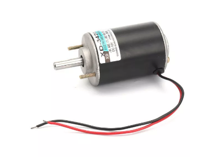 |
| 12V/24V 30W generator (with 6000rpm) |
Voltage Sensor
The primary function of the voltage sensor is to detect and measure the DC voltage from the generator. When the presence of voltage is detected, the sensors provide tan output in the form of analogue voltage signals, current level, frequency and modulated frequency outputs. Below shows the voltage sensor that will use :
 |
| Voltage Sensor |
Arduino Uno
For the controller, I use the Arduino Uno in my project. The function of Arduino Uno is to display the value of voltage that being detect to LCD that be connected to the LCD. The board contains all sets of input and ouput digital and analog pins that can be used to interface with all the hardware used in this project. This Arduino Uno needed specific set of coding in order to run it perfectly. It will connected to the voltage sensor. Then the Arduino Uno will interface with the written coding and display the voltage to LCD. Figure below shows the Arduino Uno that will use :
Power Storage
The power generated from the generator will be stored in this power storage. The power storage made by lead acid battery which is rechargeable and has high capacity of stored charge. Below shows the lead acid battery that will use.
All the item that listed here will be combined to complete the project. There may be got exchange of item that will use depends on the situation of the project.
 |
| Arduino Uno |
The power generated from the generator will be stored in this power storage. The power storage made by lead acid battery which is rechargeable and has high capacity of stored charge. Below shows the lead acid battery that will use.
 |
| Lead Acid Battery |
All the item that listed here will be combined to complete the project. There may be got exchange of item that will use depends on the situation of the project.
Sunday, April 28, 2019
Week 11
This week I tried to design the turbine that will use in my micro power generator. I tried to learn and use several software to design by using SketchUp. Below shown the SketchUp software.

Below shown the design of turbine that been made by using SketchUp. There a lot of things need consider when designing the turbine which is the size of the turbine, the angle of the blade's turbine and the shape of the turbine. We need to make sure that the size of the turbine is fit in the water pipe. Also the angle of blade's turbine need to pay off attention. If the angle was not properly make, then the turbine will not rotate by the pressure and the flow rate of water.
 |
| 1st Design |
 |
| 2nd Design |
Saturday, April 13, 2019
Week 10
Material of Turbine Blade
I continue my progress of making turbine.
Building my full size turbine from composite material chosen for 3 reason :
I continue my progress of making turbine.
Building my full size turbine from composite material chosen for 3 reason :
- Mechanical (Strength)
- Corrosion Resistance
- Cost
From characteristic above, I got several choice of material to make the turbine which is :
martensitic stainless steel, 3D printing or fiber glass. All 3 of this got its own pros and cons. Below shown the characteristic of each material :
 From table above, there were many things that need to be considered before i make the decision. From what we can see, the easiest one to make the turbine is by using 3D printing. But, I am not sure if that turbine can works as the way as it need to be without affect its performance. If we want to make by using fiber glass, it need a very high cost and need to have a specific way of doing it. As for Martensitic Stainless Steel, it also have an expensive cost from making it. But it still can be make because it has a low weld-ability to making it. I still not making choice for the material of turbine since I did not done yet my research on it. After I done my research, I will inform at another day.
martensitic stainless steel, 3D printing or fiber glass. All 3 of this got its own pros and cons. Below shown the characteristic of each material :

Wednesday, April 10, 2019
Week 9
Workshop
For this week, we had FYP Workshop 2. The workshop was conducted at TTL2
The Workshop is about to give explanation for the student for the students who taking the final project for Degree programmes for the proposal report of FYP 1. The workshop is about :
Calculation of Micro Hyropower
I also learn about how to calculate the power generated by the micro hydro-power. This was very importance because it is to know if the turbine that been made can withstand the pressure and water flow rate in the water pipe. If the pressure and water flow rate are big, the turbine will breakdown and can't work properly. Below shown the formula of calculation of micro hydro-power :
For this week, we had FYP Workshop 2. The workshop was conducted at TTL2
The Workshop is about to give explanation for the student for the students who taking the final project for Degree programmes for the proposal report of FYP 1. The workshop is about :
- Methodology (Chapter 3)
- Preliminary Result (Chapter 4)
- Abstract Writing
Calculation of Micro Hyropower
I also learn about how to calculate the power generated by the micro hydro-power. This was very importance because it is to know if the turbine that been made can withstand the pressure and water flow rate in the water pipe. If the pressure and water flow rate are big, the turbine will breakdown and can't work properly. Below shown the formula of calculation of micro hydro-power :
P = η
* Q * g * h
Where :
P : Power, measured in Watts (W)
Overall
η : The product of all of the component efficiencies, which are normally the turbine, drive system and generator
Q : Flow rate of water
g : The gravitational constant, which is 9.81m/s2
hnet : the net head. This is the gross head physically measured at the site, less any head losses. To keep things simple head losses can be assumed to be 10%
Expected Calculation
Below also shown the expected calculation that been made for the expected output of power generated.
 |
| Expected calculation that used the calculation |
Friday, April 5, 2019
Week 8
For this week, I started to make research about the turbine that I want to use. This was the most important part of my research for my project. Below was the things that needed to highlight for the turbine :
Type of Turbine Used
- Type of turbine used
- Material of turbine blade
- How the turbine function
- Environment issue
Flowing water is directed on to the blade of turbine runner, creating a force on the blades. Since the turbine is spinning, force acts through a distance, the energy is transferred from water flow to turbine.
There were 2 type of turbine which is Reaction Turbine and Impulse Turbine. Reaction turbine are acted on by the water, which changes pressure as it move through the turbine and give up its energy. They must be encased to contain the water pressure or they must be submerged in the water flow. Impulse turbine change the velocity of the water jet. The jet pushes on the turbine's curved blades which changes the direction of flow. The resulting change in momentum caused a force on the turbine blades.
For my project, I decided to use Reaction type of turbine which submerge in the water pipe. The type is Gorlov Helical Turbine.
Gorlov Helical Turbin
Gorlov Helical Turbine (GHT) is a turbine that designed by altering it to have helical shape. Term of "foil" is used to describe the shape of the blade cross-section at the given point, with no distinction for the type of fluid. By using this shape, the turbine generates a smoother torque curve, so there is much less vibration and noise. The GHT has been observed to have up to 35% of efficiency in energy capture.Below show the original shape of GHT :

For my project, I will change the GHT and make it into spherical-helical's shape turbine. Since my project was in the water pipe, so the turbine should be in spherical shape. This will make the turbine rotate much faster due to the shape. The rotation of turbine will generate voltage by cutting the magnetic flux at rotor and stator. Below shown the spherical-helical turbine that I will use :

As for the material of turbine blade, I still doing research on which material is suitable for being used without messing up the performance of turbine.
Gorlov Helical Turbine (GHT) is a turbine that designed by altering it to have helical shape. Term of "foil" is used to describe the shape of the blade cross-section at the given point, with no distinction for the type of fluid. By using this shape, the turbine generates a smoother torque curve, so there is much less vibration and noise. The GHT has been observed to have up to 35% of efficiency in energy capture.Below show the original shape of GHT :


As for the material of turbine blade, I still doing research on which material is suitable for being used without messing up the performance of turbine.
Wednesday, March 20, 2019
Week 7
For this week, we had FYP Workshop
The workshop was conducted at TTL2
The Workshop is about to give some further explanation for the student for the students who taking the final project for Degree programmes for the proposal report of FYP 1. The workshop is about :
The workshop was conducted at TTL2
The Workshop is about to give some further explanation for the student for the students who taking the final project for Degree programmes for the proposal report of FYP 1. The workshop is about :
- Introduction (Chapter 1)
- Literature Review (Chapter 2)
Decision of Type & Size of pipe
For this week, I finalize the type of pipe used in my project. i will use PVC pipe because it easier to handle sturdy. Although it easier to break down, it will not a problem because the pipe are not put at easy-break place. As the size of pipe, I will use the nominal 4 which is O.D Inches are 4.5. This is because the pressure in water pipe will affect the turbine performance and water flow. If the size of pipe is big, the water flow will become slow and pressure will low. Below was the size of pipe :
 |
| Nominal & O.D |
Friday, March 15, 2019
Week 6
For this week, I'm doing research about the pipe. When talking about pipe, there were a lot of thing that need to be considered such as the type of pipe. A lot kind of pipe that had been made such as PEX Pipe, PVC pipe, Rigid Copper Pipe, ABS Pipe, Flexible Copper Pipe, Galvanized Steel Pipe and Case Iron Pipe. A lot of pros and cons in this kind of pipe. As for my project, I'm using PVC pipe.
Type of Pipe
PVC stands for polyvinyl chloride. Of the different types of plastic pipe used for water supply, PVC has a wide variety of plumbing uses, from drainage pipe to water mains because it has lighter and easier to work with than traditional galvanized steel pipe. PVC pipe is moderately easy to install and requires little more than hacksaw and mitre box to cut. PVC glues together with solvent. Below listed the pros and cons of PVC pipe.
Pros
Pressure
We also need to take note about the flow of water in the water pipe. It's because of the present of friction on the wall of the pipe. In fluid flow, friction loss (or skin fraction) is the loss of pressure or "head" that occurs in pipe or duct flow due to the effect of the fluid's viscosity near the surface of the pipe or duct. When the friction is high, the flow of water become slow thus affect the rotation of turbine. For PVC pipe, the friction on the wall is lower than galvanized steel pipe. We can calculated the friction loss between the pipe surface and the fluid flow at the physical properties of the system. These condition can be encapsulated into dimensionless number Re, known as the Reynolds number
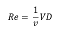 where V is the mean fluid velocity and D, the diameter of the (cylindrical) pipe. In this expression, the properties of the fluid itself are reduced to the kinematic viscosity , v
 where u = viscosity of the fluid (SI kg/m/s)
Type of Pipe
PVC stands for polyvinyl chloride. Of the different types of plastic pipe used for water supply, PVC has a wide variety of plumbing uses, from drainage pipe to water mains because it has lighter and easier to work with than traditional galvanized steel pipe. PVC pipe is moderately easy to install and requires little more than hacksaw and mitre box to cut. PVC glues together with solvent. Below listed the pros and cons of PVC pipe.
Pros
- Diameters clearly marked on the white surface of the pipe.
- Inexpensive and can be used for long runs such as for irrigation.
- Flexible
Cons
- Pipe cannot be unjoined and must be cut
- Glued pipes can be prone to be leaking
- Fragile and tends to shatter.
We also can use galvanized type of steel/iron pipe but it got greater problem where the flow of water become slow or static for periods of time due to rust discoloration caused by internal corrosion. This type of pipe only used in older homes. This will nit used for water supply in new construction or remodel projects.
 |
| Type of pipe |
Pressure
We also need to take note about the flow of water in the water pipe. It's because of the present of friction on the wall of the pipe. In fluid flow, friction loss (or skin fraction) is the loss of pressure or "head" that occurs in pipe or duct flow due to the effect of the fluid's viscosity near the surface of the pipe or duct. When the friction is high, the flow of water become slow thus affect the rotation of turbine. For PVC pipe, the friction on the wall is lower than galvanized steel pipe. We can calculated the friction loss between the pipe surface and the fluid flow at the physical properties of the system. These condition can be encapsulated into dimensionless number Re, known as the Reynolds number
Friday, March 8, 2019
Week 5
Registration of FYP's tittle
This week was the last week to register the tittle of FYP. I went to see Dr. Reyasudin once again to remind and comfirmed my tittle to him. Dr. Reyasudin registered my name and tittle of the project under his supervision on the FYP website. I should be able to check the application status online once the supervisor approve my application.now, I am officially under supervision of Dr. Reyasudin for my FYP. As my supervisor, Dr. Reyasudin will guide me in this project, recommend method and techniques to achieve the project's objective.
Research and Finding
For this project, I had come out with a flow chart diagram for prototype that showed the process and step.
 |
|
Friday, March 1, 2019
Week 4
Registration on FYP tittle
In this week, I went to see Dr. Reyasudin. After a lot of thinking and doing research, I choose to do my one on my tittle before which is "Development on Power Generator in Water Pipe". At there, we discussed about my research that Dr. Reyasudin asked me to do. I explained all the things that I search about my tittle. In the end, we confirmed my FYP's tittle. Thus, my finalized title is "Development of Micro Power Generator in Water Pipe". Dr. Reyasudin will register my tittle in UniKL BMI's FYP website for further step. I would like to thanks Dr. Reyasudin for his help in determined my FYP tittle.
Synopsis of the project
This project is to study, design and develop a prototype of turbine and generator that will function in water pipe. I am doing this project after research about how Malaysia got a big potential of making hydro power generator without using dam. This project will be used at the river of remote area to supply electricity for the villagers. As for the turbine, I will design a turbine that will working properly in the water pipe. The basic concept in this generator is by cutting the magnetic flux from rotor and stator. When the water flow, the turbine will spin which lead to cut the magnetic flux from rotor and stator. From the cutting the magnetic flux, we will get the generated power and it will stored in power storage.
Subscribe to:
Posts (Atom)